In-Cylinder Fiber-Optic Pressure Sensors for Monitoring and Control of Diesel Engines
M. T. Wlodarczyk, T. Poorman, L. Xia, J. Arnold, and T. Coleman
OPTRAND INC.
ABSTRACT
The use of real time cylinder pressure information in advanced diesel engine monitoring and control techniques offers the potential for improved engine reliability and performance as well as reduced levels of emissions. This paper reports the design and performance of Optrand high-temperature, long-life, and miniature fiber-optic pressure sensor that has been specifically developed for engine control and monitoring applications. For use in automotive diesel engines the sensor is preferably integrated with a fuel injector or a glow plug. Laboratory and various engine tests are reported here for small and large diesel engines demonstrating a typical +/-0.5% total error due to non-linearity, hysteresis, and thermal shock. In various engines the sensor has already demonstrated the unprecedented lifetime of 0.8 Billion-pressure cycles.
Cylinder pressure is the fundamental variable that determines a combustion engine’s operating state. In particular, combustion pressure information can be used in advanced engine control and monitoring systems, if available continuously and in real-time. Based on cylinder-specific pressure information, closed-loop control applications have been proposed for power balancing in large-bore natural gas engines, lean burn combustion in passenger cars, or stall control in aircraft engines. The most advanced controls each cylinder and each combustion cycle are controlled in what has been termed the Controlled Combustion Engine (CCE).
While a sizable literature exists on various control strategies in spark ignited engines [1], little information is available on cylinder pressure sensor use to control diesel engines. So far the detection of start and end of combustion events has attracted the most attention [2], to reduce NOx, smoke, and soot emissions. The more recent interest has been in Air-Fuel ratio control [3] for turbocharged engines, mostly in the interest of reducing the NOx levels.
Most of the diesel engine use of cylinder pressure sensors has been, however, in the area of engine balancing and monitoring. Larger diesel engines, typically with 8 or more cylinders, are frequently prone to cylinder to cylinder variability requiring periodic re-balancing and frequent adjustments. In some older marine engines, periodic balancing as frequent as every single month is required to maintain nominal engine operating and emission characteristics.
Recently cylinder pressure monitoring has become popular in the area of Condition Based Maintenance (CBM) [4]. The US Navy in particular has been pursuing the concept of "smart ship" attempting to eliminate the traditional scheduled maintenance in favor of CBM. Based on cylinder pressure evolution over time various diagnostic and prognostic techniques have been reported leading to early detection of such problems as piston scuffing, overheating, cracking of cylinder heads, fuel injection system failures, or bearing failure.
To date the widespread use of cylinder pressure based monitoring and control systems has been hampered by one overriding factor: the lack of a cost-effective, reliable, and durable combustion pressure sensor. Piezoelectric-quartz pressure transducers that have been used over decades in engine development and calibration are not suited for implementation in production engines. They are subject to electromagnetic interference (EMI) effects, have limited lifetime, and are unacceptably expensive. Lower cost piezoceramic devices, such as spark plug washers and boss-type sensors, do not offer high accuracy under all engine conditions, are subject to electrical interference problems, and are prone to large temperature errors. In addition, their durability is not sufficient for use in production engines as a consequence of degrading effects of alloy segregation, selective oxidation, and diffusion.
Newly available piezoresistive Silicon combustion pressure sensors have potential for use in production engines [5]. They utilize a low-cost piezoresistive element, which must be maintained below a temperature of 125oC, connected to the sensor diaphragm via a transfer pin. However, these types of sensors require a separate access point into the engine’s head as well as special mounting location for water-cooling and non-disruption of oil passages. In modern four-valve engines there is no space available for a separate sensor. Furthermore, piezoresistive sensors are subject to EMI, are large in size, have not shown long lifetime, and are too expensive at present. Due to the above limitations, the piezoresistive sensors have found very limited use in production engines.
Silicon Carbide (SiC) based sensors, such as recently reported by a team from Daimler Benz, target operations at temperatures as high as 500oC [6]. Unlike in Silicon devices where the sensing diaphragm and the processing electronics are spatially separated, SiC sensors aim at combining the both functions into a single compact device. However, SiC sensors suffer form a number of limitations of other electronic devices including susceptibility to EMI, lead oxidation, as well as lifetime problems related to long-term diffusion and phase segregation effects at high temperatures. The reported devices demonstrated relatively poor performance in particular in the area of temperature errors as large as 20%. Finally, the SiC material itself is prohibitively expensive and its processing techniques are complex and expensive as well.
In contrast to electronic devices, fiber-optic sensors are potentially very well suited for applications characterized by high temperatures and high levels of EMI encountered in combustion engines [7]. These benefits combined with exceptional durability and very low cost make fiber optical sensors prime candidates for use in automotive production engines. Due to their miniature size, resistance to high temperatures, and immunity to EMI, these sensors can be combined with existing engine components such as ignition spark plugs, fuel injectors, or glow plugs. Such multifunctional devices with an embedded pressure sensor offer numerous advantages for practical and low-cost automotive systems not only from the point of view of sensor expense alone but also on the account of minimum total installation and operational cost. An embedded sensor does not require a separate access point into the engine and the device that the sensor is integrated with can be conventionally installed. No additional cable or connector is needed since the pressure sensor information is sent via the existing cable and connector. Connecting multiple non-embedded sensors to the engine controller represents a complex and costly task in engines with a large number of cylinders.
The low-cost fiber optic sensor developed by Optrand for combustion engine applications consists of three basic components: a sensing head directly exposed to combustion pressure, a fiber optic strand, and an opto-electronic module containing all sensor optical and electronic components, as shown in Fig. 1.
Fig. 1. Schematic sensor block diagram.
The opto-electronic module contains a photodiode, an LED, and a dedicated Application Specific Integrated Circuit (ASIC). Two input electrical pins are for power supply and ground while the output pin is for sensor output and fault diagnostics. The ASIC controls light intensity, amplifies and filters photodiode signal, and provides the auto referencing function. This Optrand patented technique regulates LED light intensity in response to any undesirable environmental conditions that may alter minimum detected light intensity. Baseline light intensity in fiber optic sensors may vary due to optical link transmission fluctuations resulting from connectors’ mechanical and thermal instabilities, fiber bending, light source or detector temperature dependence, or their aging over time. The auto-referencing approach not only corrects for offset drift but sensor gain error as well. A side benefit of the technique, not possible with other combustion pressure sensors, is the availability of sensor health monitoring output. By continuously monitoring the LED current level or its rate of change, one can identify potential sensor failure before it occurs. This ability is particularly important in control applications where sensor failure may cause malfunction or even failure of the controlled device.
In a simple and robust design the sensor head consists of a metal housing with a welded sensing diaphragm, a fiber holding ferrule, and two fibers bonded inside the ferrule, as schematically shown in Fig. 2. Please note that the dimensions shown in Fig. 2 are not to scale.
Fig.2 Sensor Head Construction
The sensing diaphragm is the most critical element of the sensor. It has to be as small as possible so that the embedded sensor occupies smallest amount of space in a device it is integrated with. At present our smallest size sensor has the diaphragm diameter of 2.8 mm. This small diameter creates a significant design challenge due to the simultaneous requirement of large diaphragm deflection (for high signal to noise ratio) and low stresses required for long lifetime. In a typical diesel engine application the sensor has to function reliably over 500 million pressure cycles or 1 million miles. The diaphragm reflectivity must also remain nearly unchanged over the sensor lifetime. To ensure durable operation, the present sensor uses an Optrand patented sculptured, hat-shape diaphragm with varying thickness across its diameter. A high strength alloy (Inconel) has been used as a diaphragm material. This design has been selected so it can meet fatigue life of 1 Billion cycles (possibly more) and the overpressure requirement. Other benefits of the present construction include excellent linearity of the pressure response and reduced sensitivity to direct flame and hot combustion gas effects. In addition, the diaphragm is welded to sensor housing away from the flexing area, thus improving long-term weld stability and strength.
The sensor response to pressure results from the displacement of a diaphragm that in turn changes optical signal transmitted from the sending to the receiving fiber upon reflection from the diaphragm. In a two-fiber design, light intensity collected by the receiving fiber may either decrease or increase with increasing diaphragm deflection. For a given diaphragm displacement due to a full scale pressure change the sensor response can be adjusted by a suitable choice of optical fiber core diameters and numerical apertures, as well as relative position of the fibers in respect to the diaphragm.
3. INTEGRATED SENSOR DESIGNS FOR AUTOMOTIVE ENGINES
Due to significant fuel economy improvements, direct injection systems have recently found considerable interest for use in automotive engines. Compared to those with conventional indirect (e.g. pre-chamber) injection Direct Diesel Injection (DDI) engines have a higher baseline thermal efficiency (about 40% peak), 20-35% better fuel efficiency, 10-20% lower CO2 emissions, near- zero evaporative emissions, and low cold-start emissions. Fuel economy improvement of as much as 35% has been recently reported, combined with a simultaneous increase in engine power and torque of 10%, for a Gasoline Direct Injection (GDI) engine.
A key component that is needed in both types of direct injection systems is an accurate, reliable and cost-effective fuel injector. In some high compression engines the injector may have to operate at extremely high fuel pressures (as high as 30,000 psi or 2,000 bar), provide accurate and repeatable spray patterns, and need to be precisely timed. In addition, such an injector has to operate for as many as 1 million miles and be of low-cost.
In a preferred approach a cylinder pressure sensor needed in diesel engine monitoring and control is integrated with the fuel injector. Such a "smart" injector, called PSIjetTM, can be fitted in addition with a fuel pressure sensor, for optimum performance, reliability, and low-cost, as shown in Fig. 3. The resulting device does not need to be individually balanced, as currently done, so its price can be significantly lower. Differences caused by manufacturing variability, aging, pressure line fluctuations, or fuel quality can be compensated for by using a closed-loop control of fuel timing, duration, and pressure.
Fig. 3. PSIjet Diagram |
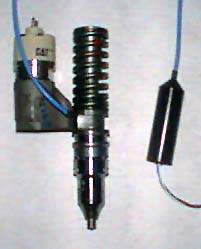
Fig. 4. PSIjet photograph |
Fig. 4 shows a picture of a prototype PSIjet with only a cylinder pressure sensor that already has been built for use in a marine diesel engine.
The PSIjet consists of five basic components: (1) two miniature fiber optic pressure sensors, one for engine cylinder and the other for fuel line pressure, (2) a modified production injector with two sensor mounting holes and fiber channels, and (3) two signal conditioning modules containing an opto-electronic module and a dedicated Application Specific Integrated Circuit (ASIC).
An alternative approach to an integrated design for diesel engine
applications is the product called the PSIglowTM, which combines
a glow plug with a miniature high-temperature fiber optic pressure sensor, as
shown in Fig. 5.
|
Fig.5. PSIglow Diagram |
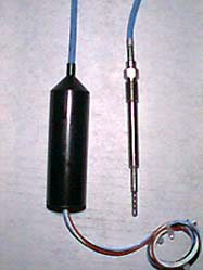 Fig. 6 PSIglow photograph |
The pressure sensing diaphragm of the PSIglow is recessed from the glow plug tip so the maximum continuous temperature of the sensor package does not exceed 350° C. Pressure access is provided on the side of the glow plug stem in the form of a series of small holes, which provide an additional functionality of a flame arrester. The production version of the product has the sensor signal conditioner embedded into the glow plug body outside of the high temperature zone and connects electrically to the ECU (Electronic Control Unit). Unlike the PSIjet, which is restricted to direct injection engine applications, the PSIglow can be used with both indirect and direct injection engines. Fig. 6 shows a photograph of the current PSIjet version with a separate signal conditioner.
4. PERFORMANCE
Differently from engine testing and R&D applications, a cylinder pressure sensor intended for engine monitoring and control does not need to be extremely accurate. The critical features are high reliability, low cost, and long life.
Typically, no individual sensor calibration is needed in the interest to lower the total system cost. However, a high degree of linearity and low-hysteresis are required within a single combustion cycle so a normalization technique can be applied based on the ratio of cylinder pressure during compression and expansion stages of the cycle.
Basic specifications of Optrand pressure sensor system intended for production engine applications are summarized in Tab.1
|
Pressure range: |
0 to 200 bar |
|
Over-pressure range: |
1.5x pressure range |
|
Linearity, hysteresis, thermal shock: |
+/-1% |
|
Frequency response: |
0.1 Hz to 30 kHz |
|
Minimum Sensor diameter: |
1.7 mm |
|
Sensor housing continuous temperature: |
-40 to 350 oC |
|
Electronics and opto-electronics continuous temperature: |
-40 to 135 oC |
|
Sensor Output: |
0.5-5 V |
|
Life time: |
500million cycles |
Laboratory testing of the sensor reported here includes linearity and hysteresis comparisons against commercially available piezoelectric sensors. Fig. 7 demonstrates a comparison of the typical room temperature dynamic pressure response, over a 0 to 70bar pressure range, of Optrand’s sensor and a reference water-cooled piezoelectric transducer (PZT) (Kistler Model 6121). The signal to noise ratio (SNR) is approximately 4000 at 15kHz bandwidth.
Below we present the series of results obtained in a test cell as well as during short- and long-term engine tests, for small and large diesel engines.
Fig. 8 demonstrates the results obtained on a single cylinder, air cooled Yanmar engine. Optrand sensor was mounted in a glow plug-like package with a water-cooled reference piezoelectric transducer mounted in the same head in proximity to the optical sensor.
Fig.8 Comparison between a glow plug-mounted sensor against a piezoelectric
reference on a single cylinder engine
|
|
|
Fig. 10 Optrand vs. Kistler sensor (Model 7613)
comparison on a commercial ship engine
|
|
The marine engine tests are reported in Figs. 9 and 10. Canadian Coast Guard obtained the results shown in Fig. 9 on an 8 cylinder Fairbanks Morse engine. Eight sensors were mounted in Kiene valves located at the end of cylinder indicator ports. It is to be noted that in spite abnormally high temperature of 400oC recorded at the mounting location, the sensors demonstrated excellent accuracy and durability.
Fig. 10 demonstrates the comparison between Optrand and Kistler sensors on a commercial ship engine. Both sensors were installed in a Kiene valve of the engine indicator port.
At the time of writing this article no data was yet available for an injector-mounted sensor. However, as good, if not better, performance is expected for an injector-mounted sensor compared to that mounted in an engine head. A sensor integrated with a fuel injector benefits substantially from the cooling effect of fuel flowing through the injector. As a consequence, the sensor body and average diaphragm temperatures are relatively low resulting in performance comparable to that of water-cooled sensors.
One of the greatest challenges in developing a combustion pressure sensor for production engine applications is the need to satisfy the sensor lifetime requirement of 10 years or 500 million pressure cycles. The harsh environment that the sensor is exposed to not only includes combustion temperatures but also vibration, widely fluctuating under-hood temperatures, and the effect of salt spray and engine fluids. We believe that the fiber optic construction of Optrand sensors makes them inherently the most durable. While the longest test to date has lasted for 12000 hours and 800 million pressure cycles, the lifetime of 20,000 hours and one billion cycles are expected for diesel engine sensors.
Fig. 11 shows a comparison between Optrand’s fiber optic pressure sensor and a reference piezoelectric transducer (Kistler Model 6121) collected approximately after 100 million pressure cycles in a lean-burn, natural gas, stationary engine. For clarity, pressure traces have been shifted vertically.
Fig.11 Comparison between Optrand sensor and piezoelectric sensor after
aproximately 100 Million pressure cycles
5. SUMMARY AND CONCLUSIONS
A durable and low-cost cylinder pressure sensor is the enabling element of advanced monitoring and control techniques for diesel engines. Optrand has developed a miniature high-temperature fiber-optic combustion pressure sensor that has all the characteristics required for production engine applications. When embedded into multifunctional devices such as "smart" fuel injectors or glow plugs the pressure sensor can be introduced into an engine without any head modifications and at minimum cost. In a robust design, the sensor utilizes the principle of light reflection from a flexing metal diaphragm, monitored by two optical fibers. Other sensor components include one LED source, one photodiode detector, and a dedicated ASIC. A smart auto-referencing technique compensates for sensor drift, fiber link fluctuations, temperature effects, and guarantees drift-free operation. The performance of Optrand diesel sensors is reported here for small, single-cylinder and large, marine engines. In a thermally optimized package the diesel sensor demonstrates combined non-linearity, hysteresis, and thermal shock errors typically of +/-0.5% Full Scale Output. So far the sensor has demonstrated approximately 800 Million pressure cycles of durability. The work is underway to evaluate a "smart" injector with a miniature fiber-optic pressure in marine engines.
6. REFERENCES
[1]. J. D. Powell, "Engine Control Using Cylinder Pressure: Past, Present, and Future", ASME J. of Dynamic Systems, Measurement, and Control, Vol. 115, pp.343-350, June 1993.
[2]. P.G. Hartman, S.L. Plee, and J.E. Bennethum, "Diesel smoke measurement and control using an in-cylinder optical sensor," SAE paper no. 910723, presented at the 1991 SAE International Congress and Exposition, Detroit, MI, Feb.-March, 1991.
[3]. U.S. patent 5,553,575, "Lambda Control by Skip Fire of Unthrottled Gas Fuel Engines", N.J. Beck, K. Gebert, H.C. Wong
[4]. R. Caccese and K. Albright, "A Common Sense Approach to Condition Based Maintenance for U.S. Navy Fleet Diesel Engines", Proceedings of the American Society of Naval Engineers Condition-Based Maintenance Symposium, Arlington, VA 1998
[5]. H.-J. Kress, J. Marek, M. Mast, O. Schatz, and J. Muchow, "Integrated Silicon Pressure Sensor for Automotive Application with Electronic Trimming" SAE paper no. 950533, presented at the 1995 SAE International Congress and Exposition, Detroit, MI, February 27 - March 2, 1995.
[6]. R. Ziermann, J. von Berg, W. Reichert, E. Obermeier, " A High Temperature Pressure Sensor Width ß-SiC-Piezoresistors on SOI-Substrates," Transducers 97, Chicago, Illinois, USA, June 16 - 19, 1997, Digest of Technical Papers, 1411 – 1414.
[7]. T. Poorman, Liangdao Xia, and M. T. Wlodarczyk "Ignition System-Embedded Fiber-Optic Combustion Pressure Sensor for Automotive Engine Control and Monitoring," SAE Paper No. 970853, 1997.
7. ACKNOWLEDGEMENT
We wish to express our thanks to Charles Gaurtier of the Transportation Development Centre, Transport Canada for his permission to use some of their data obtained on a coastguard vessel.